Features
- 1-Wire to I2C host interface with ESD protection diode.
- Use OWFS or the W1 Linux Subsystem to access your 1-Wire Devices.
- Stackable with other Raspberry Pi accessory boards.
- Buffered 5V I2C port.
- External 5V power input for the 1-Wire interface.
- I2C address selection via solder jumpers.
The 1 Wire Pi Plus is a communication board supporting the 1-Wire protocol designed for the Raspberry Pi and other compatible single-board computers.
Using OWFS or the W1 Linux Subsystem, you can access your 1-Wire devices as files within the Linux filesystem.
The 1-Wire port on the 1 Wire Pi Plus is based around a DS2482-100 I2C to 1-Wire bridge device. The DS2482-100 provides bi-directional protocol conversion between the I2C port on the Raspberry Pi and any attached 1-Wire devices. An ESD Protection Diode protects the 1 Wire Pi Plus and Raspberry Pi from electrostatic spikes on the 1-Wire® port. Connections to the 1-Wire® port can be made through the RJ-12 socket or the solder points on the PCB. We have a knowledge base article for configuring and using the 1-Wire port on your Raspberry Pi.
The 1 Wire Pi Plus is powered through the host Raspberry Pi using the GPIO port, and extended pins on the GPIO connector allow you to stack the 1 Wire Pi Plus along with other development boards.
Space is provided on the board for a 1-Wire iButton device. iButtons are small metal-packed modules that can be used for many functions, from data loggers to temperature monitoring. More information about iButtons can be found on the Maxim Integrated website. To use an iButton on the 1 Wire Pi Plus, you need to solder a DS9094F PCB clip onto the board. Please note that the DS9094F should be positioned to match the orientation marked on the PCB, and the + sign on the connector is linked to the ground side of the iButton devices.
A 5V input port allows you to use an external power supply on the 1-Wire interface, reducing the load on the Raspberry Pi. If you use the external 5V input, please remove the jumper on the board to isolate the Raspberry Pi 5V bus.
A 5V buffered I2C port is also provided on the board. Using our mounting kit pack, the 1 Wire Pi Plus can securely fit onto your Raspberry Pi.
Legacy 1 Wire Pi Versions
See our Knowledge Base article for previous versions of this board.
Technical Details
Compatibility
We have tested the 1 Wire Pi Plus on the following platforms.
| Model |
Status |
| Raspberry Pi Model A / B |
|
| Raspberry Pi 1 Model A+ / B+ |
|
| Raspberry Pi 2 Model B |
|
| Raspberry Pi 3 Model A+ / B / B+ |
|
| Raspberry Pi 4 Model B |
|
| Raspberry Pi 5 |
|
| Raspberry Pi Zero |
|
| Raspberry Pi Zero W / Zero 2 W |
|
| Raspberry Pi Compute Module 4 IO Board |
|
| Raspberry Pi 400 |
|
| Orange Pi |
|
| Asus Tinker Board |
|
| Odroid |
|
Assembly Instructions
The 1 Wire Pi Plus is supplied with the 40-pin GPIO connector, RJ12 connector, and 2-pin jumper unsoldered.
Before using the 1 Wire Pi Plus, you need to solder all three connectors onto the PCB. We suggest soldering the 40-pin GPIO connector before the RJ12 connector and the jumper. The RJ12 connector is supplied and fitted into the PCB in one of the two available positions.

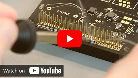
Watch our assembly guide on YouTube. (opens in a new window)
PCB Header Assembly Jig
Download and print our PCB Header Assembly Jig to hold your circuit board when soldering the header pins.
Connecting to the 1-Wire® Port
The 1-Wire® port on the 1-Wire Pi can be accessed through the female RJ12 socket or the solder points on the PCB. An ESD protection diode is fitted between the RJ12 port and the 1-Wire® interface IC.
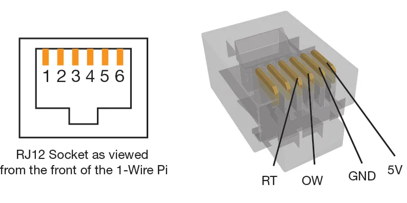
The pinout connections for the RJ12 port are shown below:
- Pin
- Usage
- 1
- 5V
- 2
- Ground
- 3
- OW (1-Wire® Data, ESD Protected)
- 4
- RT (1-Wire® Return/Ground, ESD Protected)
- 5
- NC
- 6
- NC

I2C Address Selection
The 1 Wire Pi Plus includes two address selection solder jumpers which can be bridged with solder to give you up to 4 different I2C addresses.
Configuration 1:

Configuration 2:

Configuration 3:

Configuration 4:
