combining the 5v & GND pins with the IO Pi Plus
The ADC Pi is an Analogue to Digital converter for the Raspberry Pi
18/09/2018
Posted by:
mathijs
![]()
For my project i stacked one IO Pi Plus with two ADC Pi Plus. I unlinked the IO pi Plus by unsoldering the link, so I can power it with an external 5v power suply. I now want to power the ADCs with the same power suply. The ADC Pi Plus boards however don't have link solders. Can I stil hook up all the 5v (the onces next to the input row on the ADC, and the 5v next to bus 2 on the IO plus)? Or are the ADC's powered from the raspberry and will i fry something if i hook it up like this?
Thanks in advance for your help! loving the boards!
18/09/2018
Posted by:
andrew
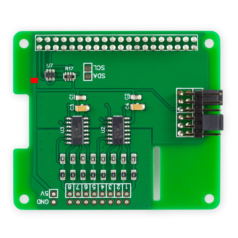
To power the ADC Pi Plus boards from an external supply you will need to cut the PCB trace on the board which connects to the 5V GPIO pin on the Raspberry Pi. This will isolate the ADC Pis 5V input preventing your external supply from feeding through to the Raspberry Pi. The red box on the photo below shows which trace needs to be cut.

18/09/2018
Posted by:
mathijs
![]()
Is that advised above just powering it with the raspberry? I could also only power the one IO Pi Plus with the external power, and the ADC's through the raspberry.
18/09/2018
Posted by:
andrew
Cutting the PCB trace as shown in the photo isolates the ADC chips and the I2C level translator from the Raspberry Pis 5V supply which will allow you to power the ADC Pi by connecting it to your external supply using the 5V and GND pins next to the ADC inputs.
One thing worth noting is the accuracy of the ADC inputs is dependent on the stability of the power supply so if your external supply is more stable with less noise than the Raspberry Pis power supply then you may see an improvement in the accuracy of the ADC measurements.
18/09/2018
Posted by:
mathijs
![]()
Note: documents in Portable Document Format (PDF) require Adobe Acrobat Reader 5.0 or higher to view.
Download Adobe Acrobat Reader or other PDF reading software for your computer or mobile device.
