power supply and reference voltage
The ADC Pi is an Analogue to Digital converter for the Raspberry Pi
03/11/2015
Posted by:
josef
I am using the ADC Pi plus board as a field data logger.
Power supply is a UBEC 5V@3A (from Adafruit) and the raspberry pi (B+) has a USB modem for data transfer.
I recently found that I get lower readings from the ADC Pi plus when the modem connects to internet. It seems that it is because of the increased load on USB-ports and thereby slightly lower ouput voltage from the UBEC.
I thought the onboard voltage reference would make the readings independent of power supply voltage but I must have misunderstood how this works.
Here is a plot showing a simple test:
adc2 - the power supply from UBEC (with external voltage divider)
adc3 - external constant voltage generator
not shown in plot:adc1 - external power (pre UBEC) adc4-adc8 - connected to ground
How can I get stable readings from external signals, independently of smaller variations in the power supply?
Thanks!
04/11/2015
Posted by:
andrew
The ADC chip on the ADC Pi Plus does use an internal voltage reference for making voltage measurements but sudden voltage changes in the power supply could cause errors in the reading due to the way the ADC works. The ADC performs a self-calibration of offset and gain for each conversion but if a change in voltage on the power line occurs between the self-calibration and the sample is taken then a reading error could occur.
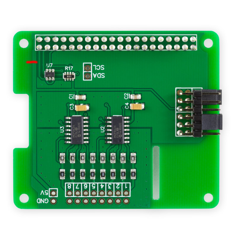
There may be a few things you can try to reduce the problem. The ADC Pi Plus has 5V and GND pins on the board, you could try connecting your power supply to those pins as well as to the Raspberry Pi itself. This will increase the amount of current available to the ADC Pi and Raspberry Pi but the downside is the fuse on the Raspberry Pi will be bypassed so you will have to be more careful when using the Raspberry Pi as there won't be any overcurrent protection if you short one of the GPIO pins to ground.
Adding some large capacitors to the power line will also help reduce voltage fluctuations as they will be able to supply the extra current needed when the modem is being used.
If the problem still occurs then one other thing you could try is to use a second smaller power supply to provide 5V to the ADC Pi Plus independent of the Raspberry Pi. To do this you will need to cut the 5V trace on the PCB as shown by the red line in the image below and then connect the second power supply to the ADC Pi Plus 5V and GND pins. This will isolate the power for the ADC Pi Plus from the Raspberry Pi so any voltage drops on the Raspberry Pi will not affect the ADC Pi Plus. The ADC Pi Plus uses a voltage level translator for the I2C pins so as long as both power supplies share a common ground the ADC Pi Plus should still be able to communicate with the Raspberry Pi.

05/11/2015
Posted by:
josef
06/11/2015
Posted by:
andrew
If you are using our python library then you can use the set_conversion_mode(1) function to change the ADC to continuous conversion mode.
Changing the bit rate to a lower rate may also help as it will mean there are more samples being taken so it should stabilise faster.
25/11/2015
Posted by:
josef
I just thought that I'd let you know the set_conversion_mode(1) made no difference. See linked figure where I switch to continuous mode at 13:31.
figure
I will try your other suggestion with a separate power supply as soon as possible
Note: documents in Portable Document Format (PDF) require Adobe Acrobat Reader 5.0 or higher to view.
Download Adobe Acrobat Reader or other PDF reading software for your computer or mobile device.
