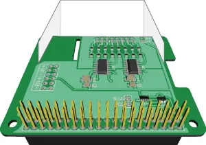
The ADC DAC Pi Zero is a 2-channel 12-bit analogue-to-digital converter and a 2-channel 12-bit digital-to-analogue converter designed to work with the Raspberry Pi and other compatible single-board computers. Designed for the same footprint as the Raspberry Pi Zero, the ADC DAC Pi Zero is also compatible with full-size Raspberry Pi models.
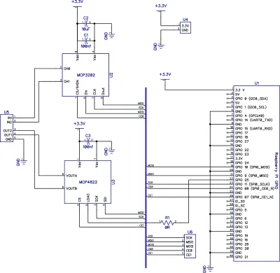
The ADC DAC Pi Zero is based on the Microchip MCP3202 A/D converter containing 2 analogue inputs with a 12-bit resolution and a Microchip MCP4822 dual channel 12-bit DAC with internal voltage reference.
Power to the board is provided through the host Raspberry Pi using the GPIO port. Only one ADC DAC Pi Zero can be used on a Raspberry Pi, but the extended pins on the GPIO connector allow you to stack the ADC DAC Pi Zero along with other development boards. Using our mounting kit, you can securely fit the board on your Raspberry Pi. As the ADC DAC Pi Zero uses the same footprint as the Raspberry Pi Zero, only two mounting holes can be used on the larger Raspberry Pi models.
The A/D and D/A converters communicate with the Raspberry Pi through the SPI interface.
Max ADC Sample Rate using Python library on a Pi 4: 11,000 samples per second.
Max ADC Sample Rate using C library on a Pi 4: 17,500 samples per second.
Max ADC Sample Rate using C++ library on a Pi 4: 17,500 samples per second.
Max ADC Sample Rate (based on MCP3202 datasheet): 50,000 SPS at 2.7V. 100,000 sps at 5V. ADC-DAC Pi operates at 3.3V on Raspberry Pi.
The ADC DAC Pi Zero is compatible with all Raspberry Pi models from the A+ and B+ onwards.
Not sure which ADC you need? Check our Analogue to Digital Buyers guide to compare our ADC development boards.
Technical Details
Input Ratings & Specifications
- Spec
- Ratings
- Vdd
- 3.3V
- ADC Input Voltage
- 0V to 3.3V
- Maximum ADC Input voltage
- VSS–0.6V to VDD+0.6 V
- DAC Output Voltage
- Gain = 1: 0V to 2.048V
Gain = 2: 0V to VDD
- Maximum DAC Output Current
- 25mA
- SPI voltage
- 3.3 V
3D CAD Model
 ADC DAC Pi Zero - 3D CAD File (STEP Format)
Schematic

View the schematic PDF.
Mechanical Drawings

Click the image to enlarge.
Compatibility
We have tested the ADC DAC Pi Zero on the following platforms.
| Model |
Status |
| Raspberry Pi Pico series |
|
| Raspberry Pi Model A / B |
|
| Raspberry Pi 1 Model A+ / B+ |
|
| Raspberry Pi 2 Model B |
|
| Raspberry Pi 3 Model A+ / B / B+ |
|
| Raspberry Pi 4 Model B |
|
| Raspberry Pi 5 |
|
| Raspberry Pi Zero |
|
| Raspberry Pi Zero W / Zero 2 W |
|
| Raspberry Pi Compute Module 4 IO Board |
|
| Raspberry Pi 400 |
|
| Asus Tinker Board |
|
Code Libraries and Demos
We have Python, MicroPython, C, C++, Node.js and Windows 10 IOT libraries for this expansion board. You can download all of the libraries from our GitHub repository or click on the logos below for your selected programming language.
Assembly Instructions
The ADC DAC Pi Zero is supplied with the 40-pin GPIO connector unsoldered. We provide the ADC DAC Pi Zero this way because the Raspberry Pi Zero is also supplied without a GPIO header. The ADC DAC Pi Zero can be fitted above or below the Raspberry Pi Zero.
Before using the ADC DAC Pi Zero, you need to solder the connector onto the PCB.
PCB Header Assembly Jig
Download and print our PCB Header Assembly Jig to hold your circuit board when soldering the header pins.
