The GPIO (General Purpose Input/Output) pins on a Raspberry Pi are versatile connections that allow the computer to interact with a wide variety of external devices and sensors. Each Raspberry Pi model from the Raspberry Pi B+ onwards features a 40-pin header, with 26 GPIO pins available for general use. The remaining pins provide power and ground connections, as well as specific functions like UART, SPI, and I2C interfaces. These GPIO pins can be configured as inputs or outputs, enabling the Raspberry Pi to read digital signals from sensors and switches or control LEDs, motors, and other actuators.
Our Raspberry Pi development boards use the GPIO header to communicate with the Raspberry Pi. Most of our boards only use a few GPIO pins for communication. All unused GPIO pins are available for other uses via the stacking header connector. 3.3V pins, 5V pins and ground pins used by our development boards can also be used for other Raspberry Pi Hats.
Many of our development boards use the I2C or SPI bus. In most cases, the I2C bus can also be used with other I2C devices on the Raspberry Pi as long as the I2C address does not conflict with the development board. The SPI bus can only be used by one development board.
Details of the pins used by our development boards can be found below. The physical pin number along with its use is included.
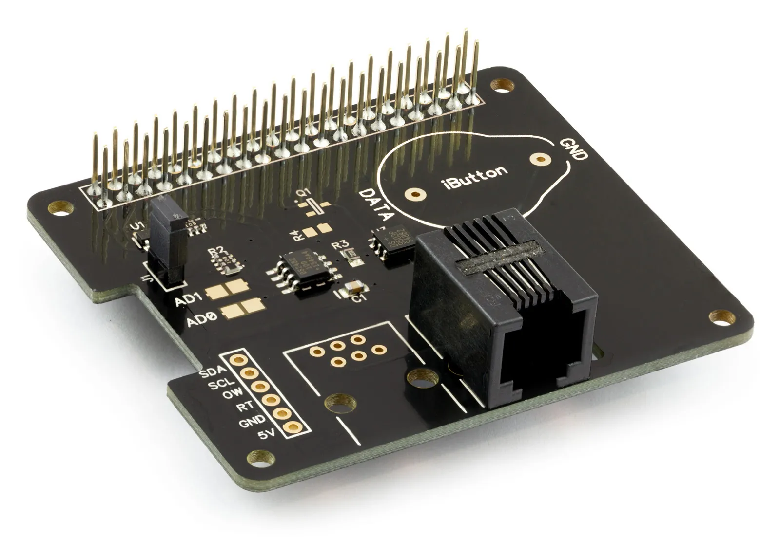
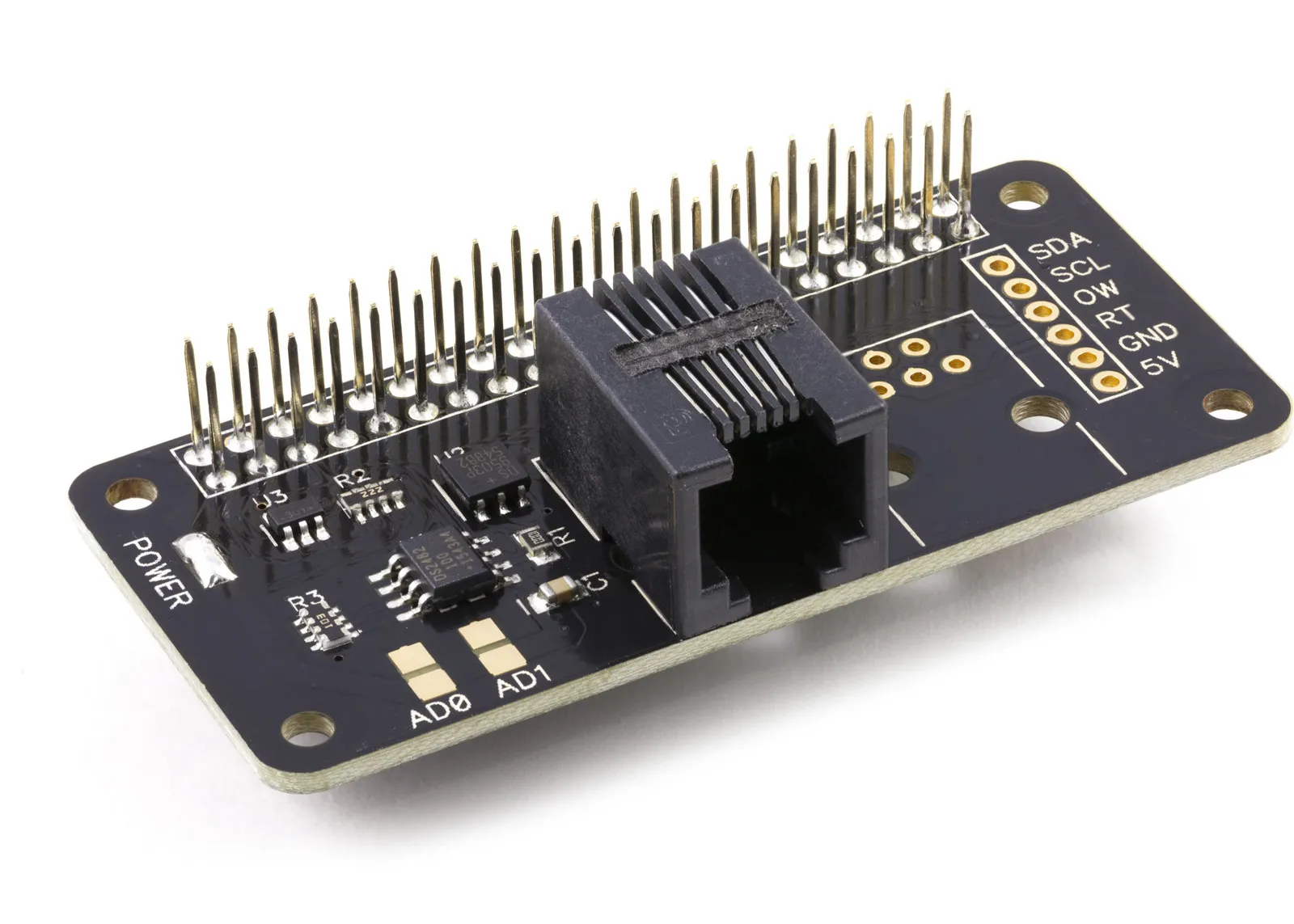
1 Wire Pi Plus and 1 Wire Pi Zero GPIO Pins
The 1 Wire Pi Plus and 1 Wire Pi Zero use the following GPIO pins.
| Pin | Use |
|---|---|
| 1 | 3.3V |
| 2 | 5V |
| 3 | I2C SDA (GPIO 0) |
| 4 | 5V |
| 5 | I2C SCL (GPIO 1) |
| 6 | GND |
| 9 | GND |
| 14 | GND |
| 20 | GND |
| 25 | GND |
| 30 | GND |
| 34 | GND |
| 39 | GND |
The default I2C address is 0x18. The following I2C addresses can be selected using the address select jumpers.
- 0x18
- 0x19
- 0x1A
- 0x1B
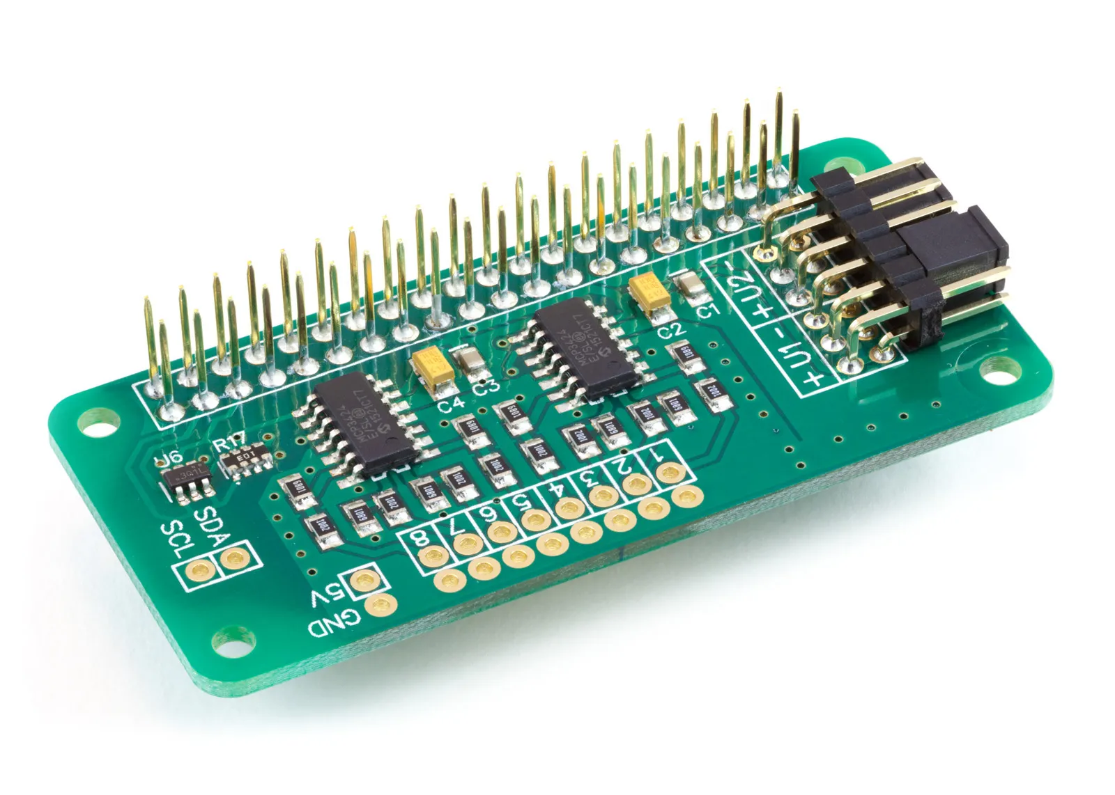
ADC Pi GPIO Pins
The ADC Pi uses the following GPIO pins.
| Pin | Use |
|---|---|
| 1 | 3.3V |
| 2 | 5V |
| 3 | I2C SDA (GPIO 0) |
| 4 | 5V |
| 5 | I2C SCL (GPIO 1) |
| 6 | GND |
| 14 | GND |
| 20 | GND |
| 30 | GND |
| 34 | GND |
| 39 | GND |
The default I2C addresses are 0x68 and 0x69. The following I2C addresses can be selected using the address select jumpers.
- 0x68
- 0x69
- 0x6A
- 0x6B
- 0x6C
- 0x6D
- 0x6E
- 0x6F
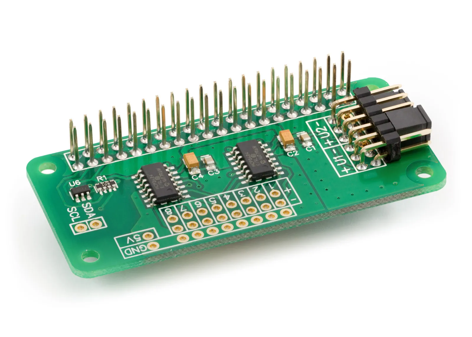
ADC Differential Pi GPIO Pins
The ADC Differential Pi uses the following GPIO pins.
| Pin | Use |
|---|---|
| 1 | 3.3V |
| 2 | 5V |
| 3 | I2C SDA (GPIO 0) |
| 4 | 5V |
| 5 | I2C SCL (GPIO 1) |
| 6 | GND |
| 9 | GND |
| 14 | GND |
| 20 | GND |
| 25 | GND |
| 30 | GND |
| 34 | GND |
| 39 | GND |
The default I2C addresses are 0x68 and 0x69. The following I2C addresses can be selected using the address select jumpers.
- 0x68
- 0x69
- 0x6A
- 0x6B
- 0x6C
- 0x6D
- 0x6E
- 0x6F
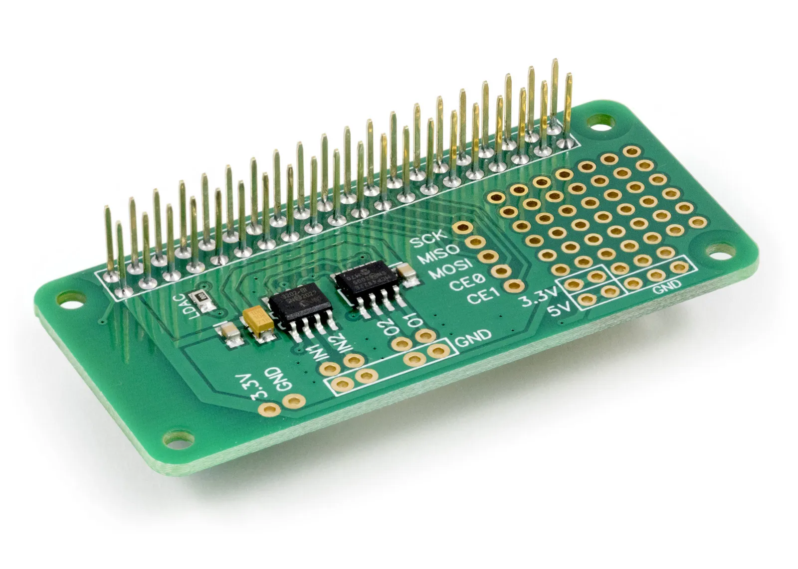
ADC-DAC Pi Zero GPIO Pins
The ADC DAC Pi Zero uses the following GPIO pins.
| Pin | Use |
|---|---|
| 1 | 3.3V |
| 6 | GND |
| 9 | GND |
| 14 | GND |
| 19 | SPI MOSI (GPIO 10) |
| 20 | GND |
| 21 | SPI MSIO (GPIO 9) |
| 22 | GPIO 25 (Note: connects to MCP4822 LDAC pin) |
| 23 | SPI SCLK (GPIO 11) |
| 24 | SPI CE0 (GPIO 8) |
| 25 | GND |
| 26 | SPI CE1 (GPIO 7) |
| 30 | GND |
| 34 | GND |
| 39 | GND |
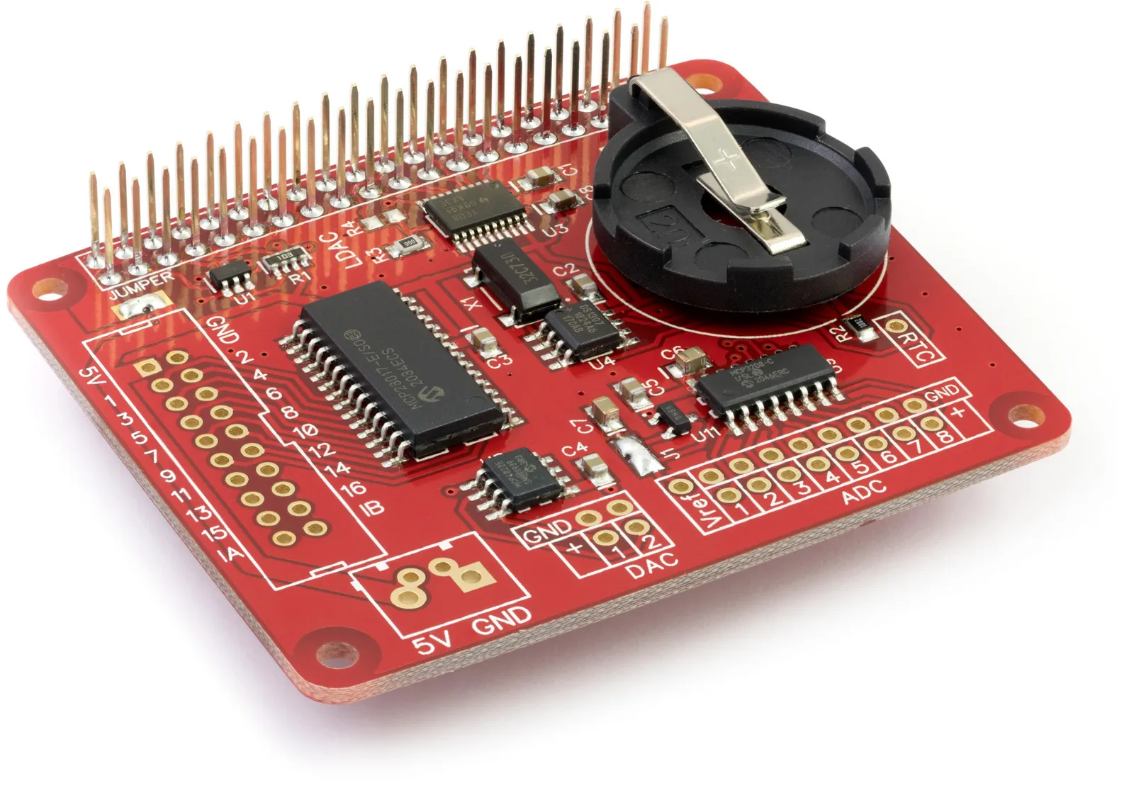
Expander Pi GPIO Pins
The Expander Pi uses the following GPIO pins.
| Pin | Use |
|---|---|
| 1 | 3.3V |
| 2 | 5V |
| 3 | I2C SDA (GPIO 0) |
| 4 | 5V |
| 5 | I2C SCL (GPIO 1) |
| 6 | GND |
| 14 | GND |
| 19 | SPI MOSI (GPIO 10) |
| 20 | GND |
| 21 | SPI MSIO (GPIO 9) |
| 22 | GPIO 25 (Note: Not connected as supplied. When resistor R3 is removed and R4 bridged this pin connects to the MCP4822 LDAC pin) |
| 23 | SPI SCLK (GPIO 11) |
| 24 | SPI CE0 (GPIO 8) |
| 25 | GND |
| 26 | SPI CE1 (GPIO 7) |
| 30 | GND |
| 34 | GND |
| 39 | GND |
The I2C address for the MCP23017 I/O controller is 0x20. The I2C address for the DS1307 RTC is 0x68.
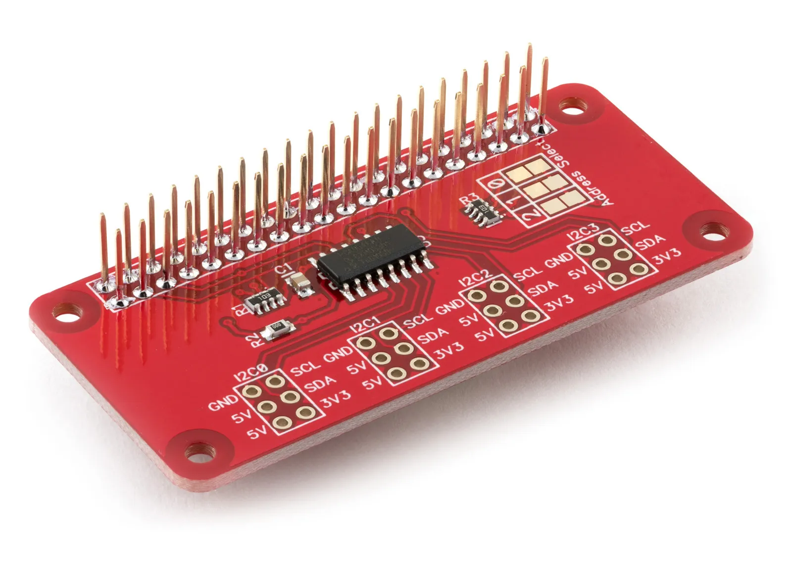
I2C Switch GPIO Pins
The I2C Switch uses the following GPIO pins.
| Pin | Use |
|---|---|
| 1 | 3.3V |
| 2 | 5V |
| 3 | I2C SDA (GPIO 0) |
| 5 | I2C SCL (GPIO 1) |
| 6 | GND |
| 13 | PCA9546A RESET (GPIO 27) (Note: this can be disconnected by removing resistor R2) |
| 14 | GND |
| 20 | GND |
| 25 | GND |
| 30 | GND |
| 34 | GND |
| 39 | GND |
The default I2C address is 0x70. The following I2C addresses can be selected using the address select jumpers.
- 0x70
- 0x71
- 0x72
- 0x73
- 0x74
- 0x75
- 0x76
- 0x77
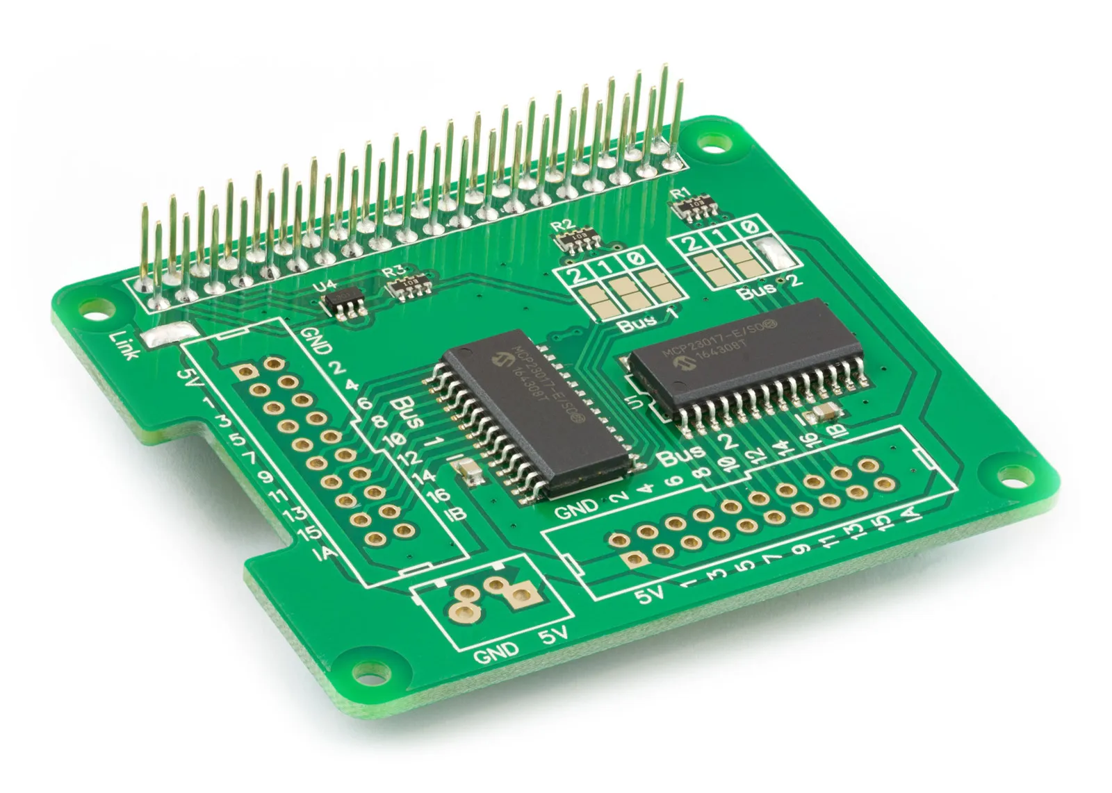
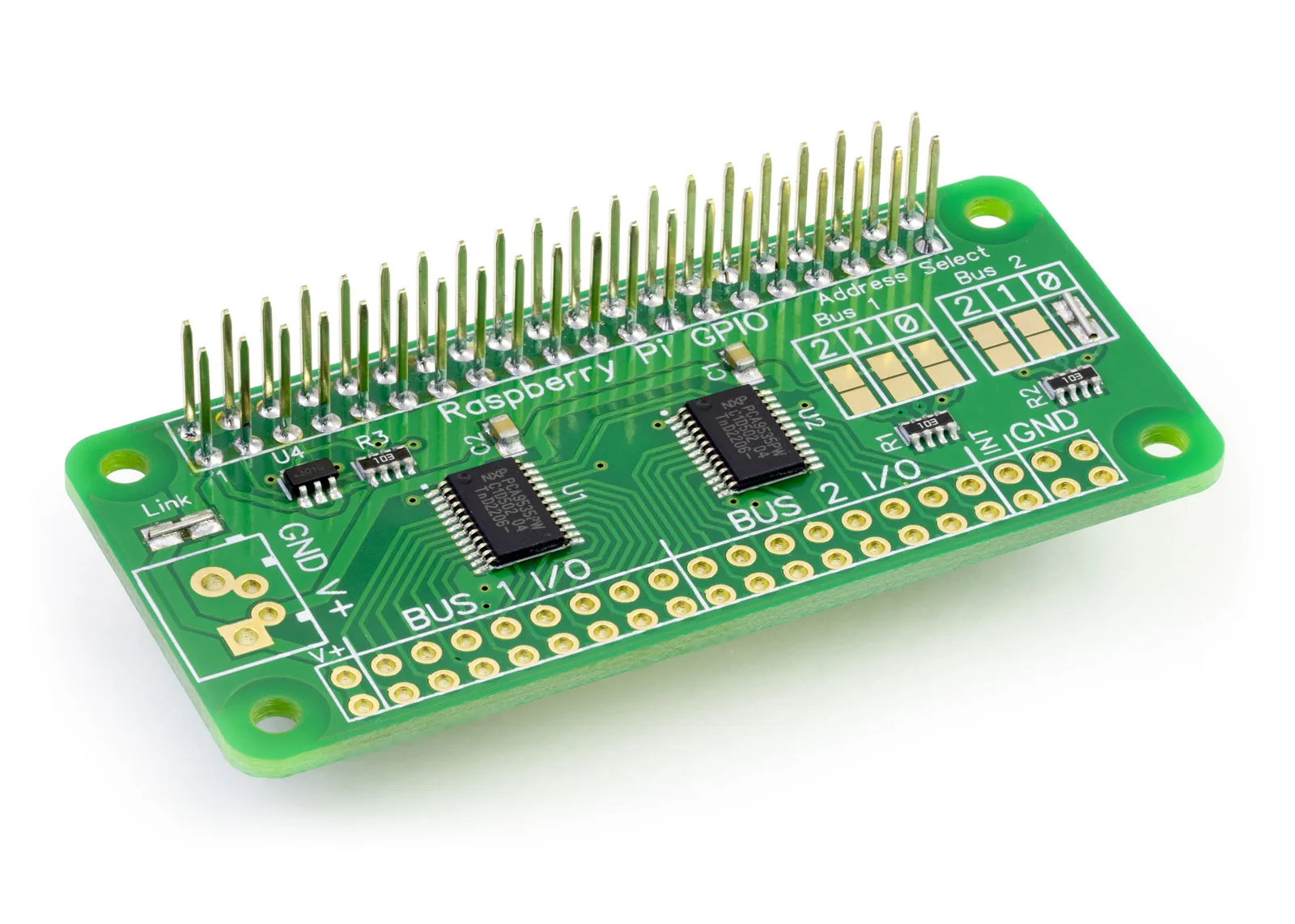
IO Pi Plus GPIO Pins
The IO Pi Plus uses the following GPIO pins.
| Pin | Use |
|---|---|
| 1 | 3.3V |
| 2 | 5V |
| 3 | I2C SDA (GPIO 0) |
| 4 | 5V |
| 5 | I2C SCL (GPIO 1) |
| 6 | GND |
| 9 | GND |
| 14 | GND |
| 20 | GND |
| 25 | GND |
| 30 | GND |
| 34 | GND |
| 39 | GND |
The default I2C addresses are 0x20 and 0x21. The following I2C addresses can be selected using the address select jumpers.
- 0x20
- 0x21
- 0x22
- 0x23
- 0x24
- 0x25
- 0x26
- 0x27
IO Zero 32 GPIO Pins
The IO Zero 32 uses the following GPIO pins.
| Pin | Use |
|---|---|
| 1 | 3.3V |
| 2 | 5V |
| 3 | I2C SDA (GPIO 0) |
| 4 | 5V |
| 5 | I2C SCL (GPIO 1) |
| 6 | GND |
| 9 | GND |
| 14 | GND |
| 20 | GND |
| 25 | GND |
| 30 | GND |
| 34 | GND |
| 39 | GND |
The default I2C addresses are 0x20 and 0x21. The following I2C addresses can be selected using the address select jumpers.
- 0x20
- 0x21
- 0x22
- 0x23
- 0x24
- 0x25
- 0x26
- 0x27
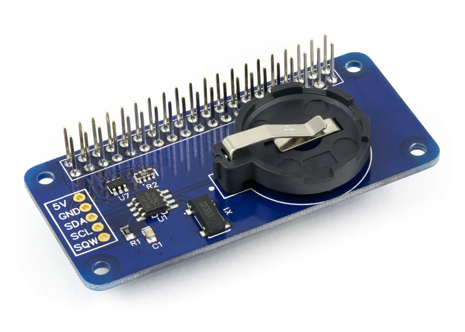
RTC Pi GPIO Pins
The RTC Pi uses the following GPIO pins.
| Pin | Use |
|---|---|
| 1 | 3.3V |
| 2 | 5V |
| 3 | I2C SDA (GPIO 0) |
| 4 | 5V |
| 5 | I2C SCL (GPIO 1) |
| 6 | GND |
| 9 | GND |
| 14 | GND |
| 20 | GND |
| 25 | GND |
| 30 | GND |
| 34 | GND |
| 39 | GND |
The I2C address for the DS1307 is 0x68.
RS485 Pi GPIO Pins
The RS485 Pi uses the following GPIO pins.
| Pin | Use |
|---|---|
| 1 | 3.3V |
| 6 | GND |
| 8 | UART0 TXD (GPIO 14) |
| 10 | UART0 RXD (GPIO 15) |
| 11 | GPIO 17 (Note: Not connected as supplied. Moving resistor R6 to R7 will connect GPIO 17 and allow control over the RE/DE pins on the SN65HVD72D via R4 and Q1. |
| 14 | GND |
| 20 | GND |
| 25 | GND |
| 30 | GND |
| 34 | GND |
| 39 | GND |
Serial Pi Plus and Serial Pi Zero GPIO Pins
For serial (UART/RS-232) projects we recommend the Serial Pi Plus board to convert the Pi’s UART to industrial-grade RS-232 interface. You can also use the Serial Pi Zero for Pi Zero based projects, both boards use the following GPIO pins.
| Pin | Use |
|---|---|
| 1 | 3.3V |
| 6 | GND |
| 8 | UART0 TXD (GPIO 14) |
| 10 | UART0 RXD (GPIO 15) |
| 14 | GND |
| 20 | GND |
| 25 | GND |
| 30 | GND |
| 34 | GND |
| 39 | GND |
Servo PWM Pi GPIO Pins
The Servo PWM Pi uses the following GPIO pins.
| Pin | Use |
|---|---|
| 1 | 3.3V |
| 2 | 5V |
| 3 | I2C SDA (GPIO 0) |
| 4 | 5V |
| 5 | I2C SCL (GPIO 1) |
| 6 | GND |
| 7 | GPIO 4 (Note: not connected as supplied. Connects to Output Enable via the OE pads. Bridge pads to connect. |
| 14 | GND |
| 20 | GND |
| 30 | GND |
| 39 | GND |
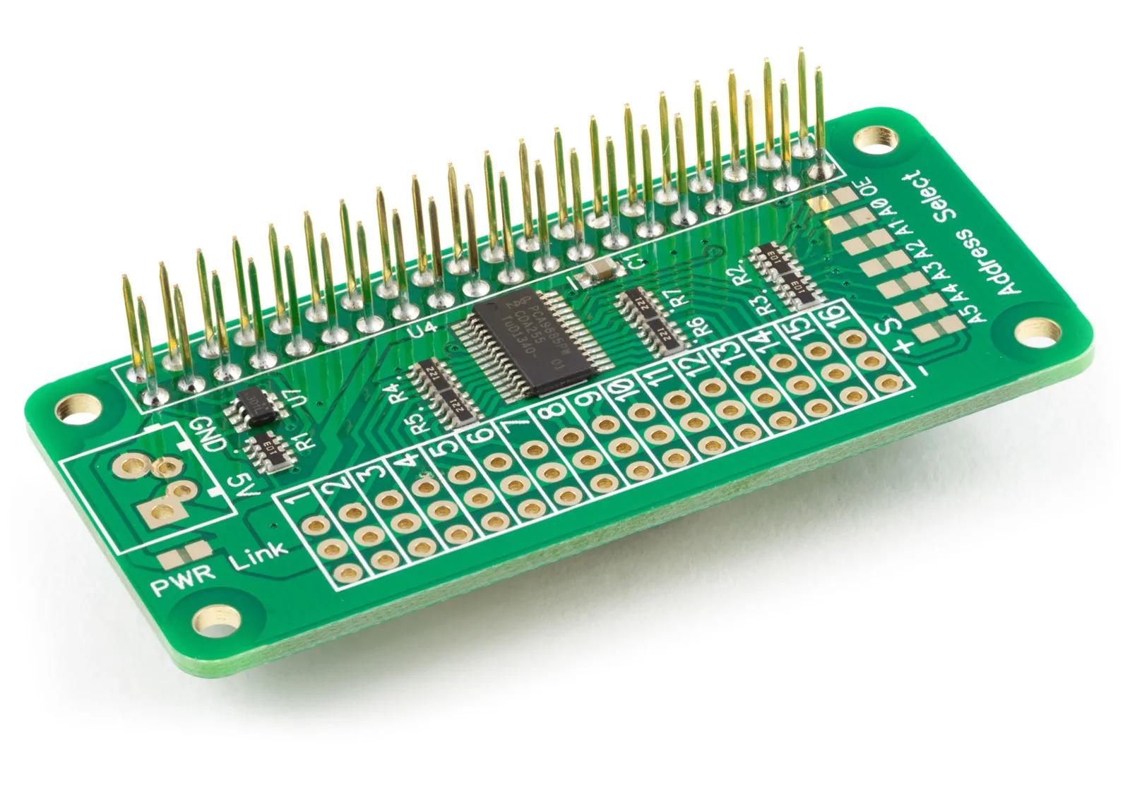
The default I2C address for the DS1307 is 0x40.
Any address between 0x40 and 0x7F can be selected using the address select pads. An additional address can be set in software for the All Call function available on the PCA9685.

