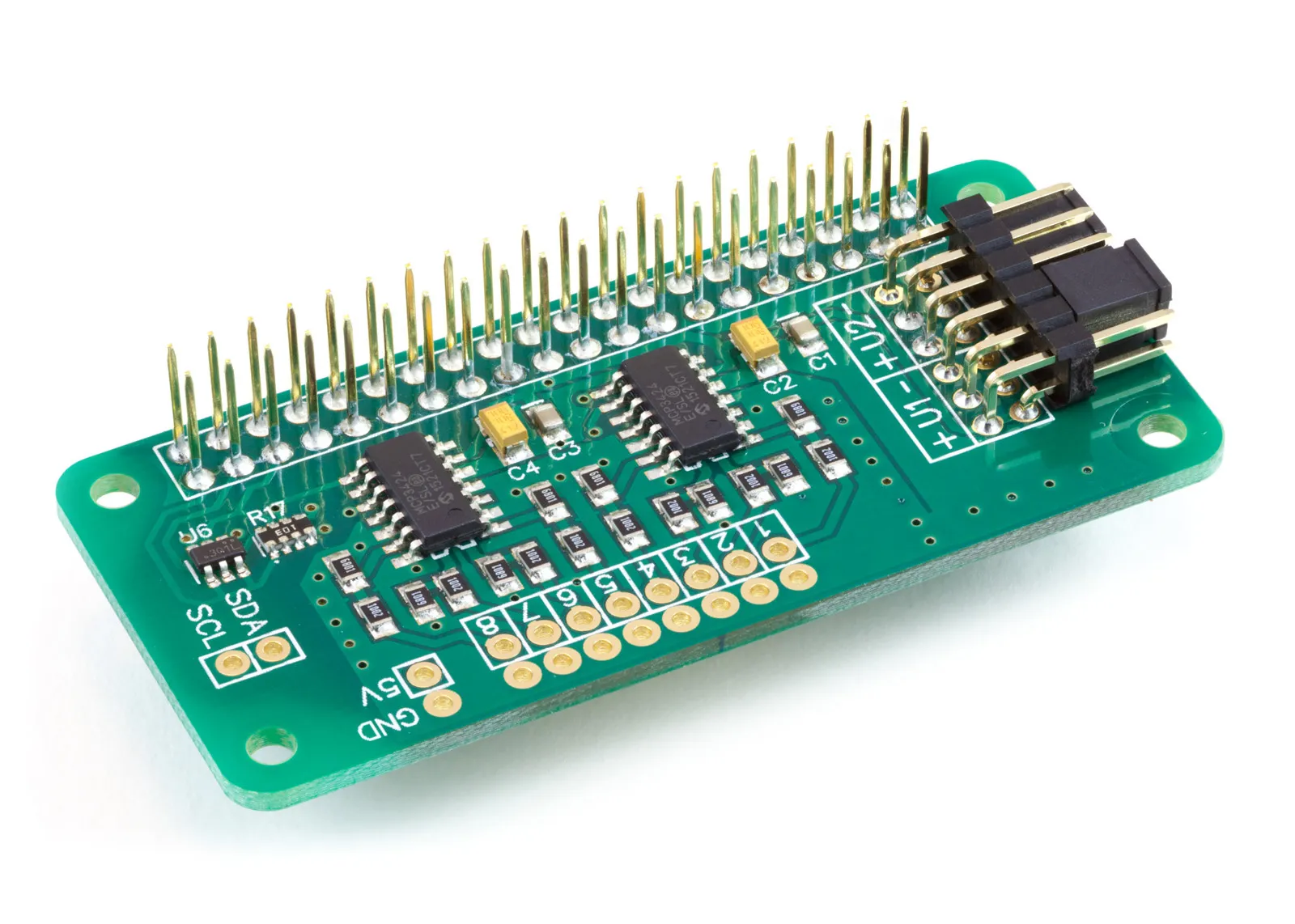
Our ADC Pi board can be used with the Raspberry Pi Pico available at Raspberry Pi
We have a MicroPython library to use with the Raspberry Pi Pico at GitHub at our MicroPython Libraries GitHub Repository
The example Python files can be found in /ABElectronics_MicroPython_Libraries/ADCPi/demos
Connecting the ADC Pi to the Raspberry Pi Pico
The ADC Pi library uses the following Raspberry Pi Pico board pins.
| Pico Pin | Pico GPIO | Function | Pi Pin | Pi GPIO |
|---|---|---|---|---|
| 26 | 20 | I2C SDA | 3 | GPIO 2 |
| 27 | 21 | I2C SCL | 5 | GPIO 3 |
| 40 | VBUS | 5V | 2 | 5V Power |
| 38 | GND | GND | 6 | Ground |
| 36 | 3V3(OUT) | 3V3 | 1 | 3v3 Power |
Wiring Diagram:
Downloading and Installing the library
To download the MicroPython library to your Raspberry Pi, type in the terminal:
git clone https://github.com/abelectronicsuk/ABElectronics_MicroPython_Libraries.git
To install the MicroPython Library, use the Thonny Python IDE.
Create a file for your chosen board and copy the contents of the Python file into that board's directory. For example, for the ADC Pi, create a new file in thonny called ADCPi.py and copy contents from ADCPi.py into the new file and save it onto the Raspberry Pi Pico board.
Create a second file where your main program will reside and import the board library at the program's top.
from ADCPi import ADCPi
Run with "Run Current Command" or F5 in Thonny.
Classes:
ADCPi(address, address2, bus)
Parameters:
address: I2C address for channels 1 to 4 defaults to 0x68
address2: I2C address for channels 5 to 8 defaults to 0x69
rate: bit rate, values can be 12, 14, 16 or 18. Defaults to 18
sda (optional): I2C SDA pin number. If no value is set, the class will use pin 20.
scl (optional): I2C SCL pin number. If no value is set, the class will use pin 21.
Functions:
read_voltage(channel)
Read the voltage from the selected channel
Parameters: channel - 1 to 8
Returns: number as a float between 0 and 5.0
read_raw(channel)
Read the raw int value from the selected channel
Parameters: channel - 1 to 8
Returns: number as an int
set_pga(gain)
Set the gain of the PGA on the chip
Parameters: gain - 1, 2, 4, 8
Returns: null
setBitRate(rate)
Set the sample bit rate of the ADC
Parameters: rate - 12, 14, 16, 18
Returns: null
12 = 12 bit (240SPS max)
14 = 14 bit (60SPS max)
16 = 16 bit (15SPS max)
18 = 18 bit (3.75SPS max)
set_conversion_mode(mode)
Set the conversion mode for the ADC
Parameters: mode - 0 = One-shot conversion, 1 = Continuous conversion
Returns: null
Usage
To use the ADC Pi library in your code, you must first import the library:
from ADCPi import ADCPi
Next, you must initialise the ADC object:
adc = ADCPi(0x68, 0x69, 18)
The first two arguments are the I2C addresses of the ADC chips. The values shown are the default addresses of the ADC board.
The third argument is the sample bit rate you want to use on the ADC chips. The sample rate can be 12, 14, 16 or 18
You can now read the voltage from channel 1 with the following:
x = adc.read_voltage(1)


