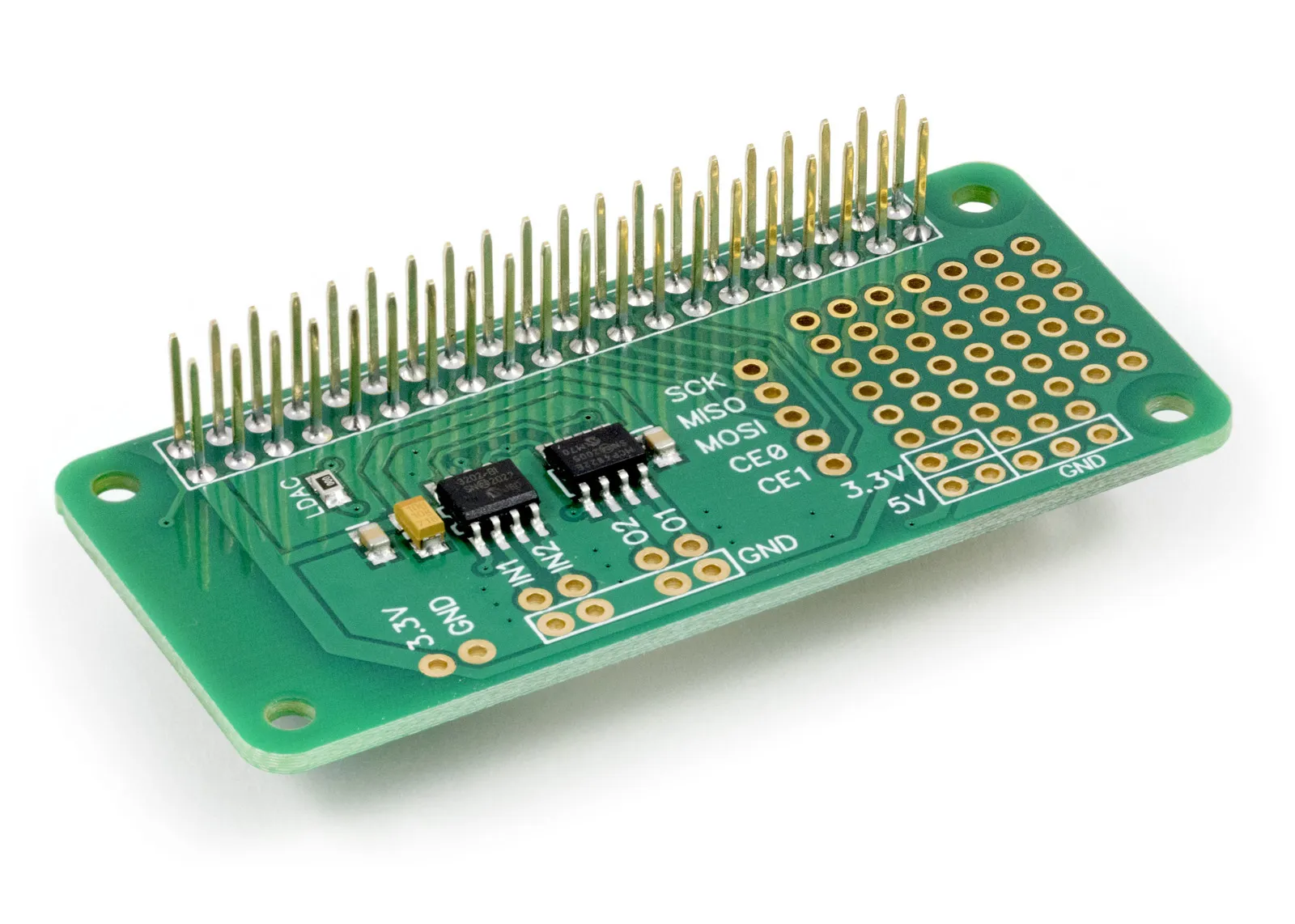
C Library to use with ADC DAC Pi Raspberry Pi development board.
The example C programs can be found in /ABElectronics_C_Libraries/ADCDACPi/demos
Downloading and Installing the library
To download to your Raspberry Pi type in the terminal:
git clone https://github.com/abelectronicsuk/ABElectronics_C_Libraries.git
Functions
open_adc()
Open the ADC SPI bus channel
This needs to be called before using the ADC
Returns: (int) 0 = SPI failed to connect. 1 = SPI connected successfully.
close_adc()
Close the ADC SPI bus channel
Returns: (int) 0 on success. On error, -1 is returned, and errno is set.
open_dac()
Open the DAC SPI bus channel
This needs to be called before using the DAC
Returns: (int) 0 = SPI failed to connect. 1 = SPI connected successfully.
close_dac()
Close the DAC SPI bus channel
Returns: (int) 0 on success. On error, -1 is returned, and errno is set.
read_adc_raw(uint8_t channel, uint8_t mode)
Read the raw value from the ADC
Parameter: (uint8_t) channel - 1 or 2
Parameter: (uint8_t) mode - 0 = Single Ended or 1 = Differential
When in differential mode, setting the channel to 1 will make IN1 = IN+ and IN2 = IN-
When in differential mode, setting the channel to 2 will make IN1 = IN- and IN2 = IN+
Returns: (uint16_t) between 0 and 4096
read_adc_voltage(uint8_t channel, uint8_t mode)
Read the voltage from the ADC
Parameter: (uint8_t) channel - 1 or 2
Parameter: (uint8_t) mode - 0 = Single Ended or 1 = Differential
When in differential mode, setting the channel to 1 will make IN1 = IN+ and IN2 = IN-
When in differential mode, setting the channel to 2 will make IN1 = IN- and IN2 = IN+
Returns: (double) between 0 and the reference voltage
set_adc_refvoltage(double ref)
Set the reference voltage for the analogue to digital converter.
The ADC uses the raspberry pi 3.3V power as a voltage reference so using this method to set the reference to match the exact output voltage from the 3.3V regulator will increase the accuracy of the ADC readings.
Parameter: (double) ref - Set this value to be the same as the voltage measured on the 3.3V GPIO pin
Returns: null
set_dac_voltage(double voltage, uint8_t channel)
Set the voltage for the selected channel on the DAC.
Parameter: (double) voltage - target DAC voltage
When the DAC gain is set to 1 the voltage will be between 0 and 2.047 volts.
When the DAC gain is set to 2 the voltage will be between 0 and 3 volts.
Parameter: (uint8_t) channel - 1 or 2
Returns: null
set_dac_raw(uint16_t raw, uint8_t channel)
Set the raw value for the selected channel on the DAC
Parameter: (uint16_t) raw - between 0 and 4095
Parameter: (uint8_t) channel - 1 or 2
Returns: null
set_dac_gain(uint8_t gain)
Set the DAC gain
Parameter: (uint8_t) gain - 1 or 2
The output voltage will be between 0 and 2.048V when the gain is set to 1, 0 and 3.3V when the gain is set to 2.
Returns: null

